4D tomography
Damage development in carbon fiber reinforced composites
The use of fiber reinforced composites has increased since the first applications in the aerospace industry in the sixties of the last century. Nowadays the combination of epoxy matrices and high-strength carbon fibers are standard materials in many industries due to their outstanding mechanical properties. The high stiffness and strength of fiber-reinforced polymer matrix composites made them suitable for several applications that range from reinforcement or retrofitting of concrete structures to structural elements in aircrafts.
Deformation mechanisms and damage development in fiber reinforced composite materials is a complex process that involves several damage mechanisms that interact together during the failure process [1-3]. The complexity of failure mechanisms lead to anisotropy and heterogeneous damage distribution in the laminates which are still subject of studies. This effect is even strengthened in more complex structural shapes or at notches.
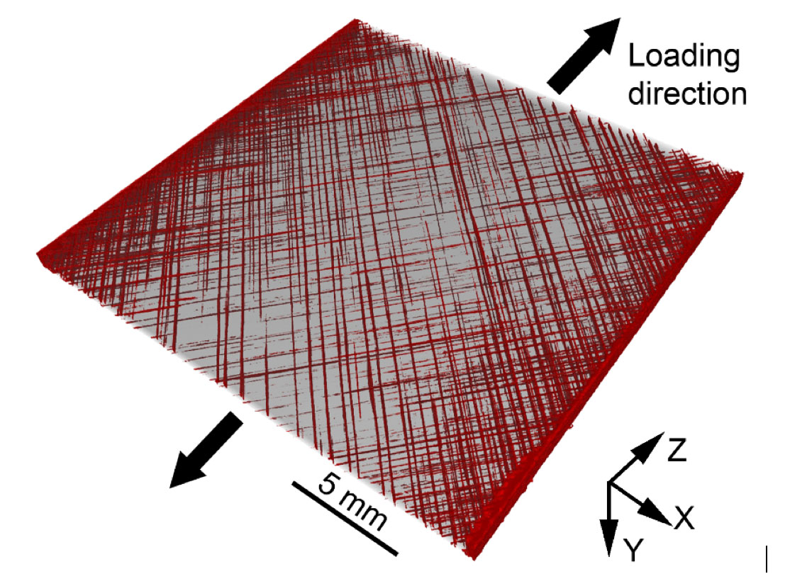
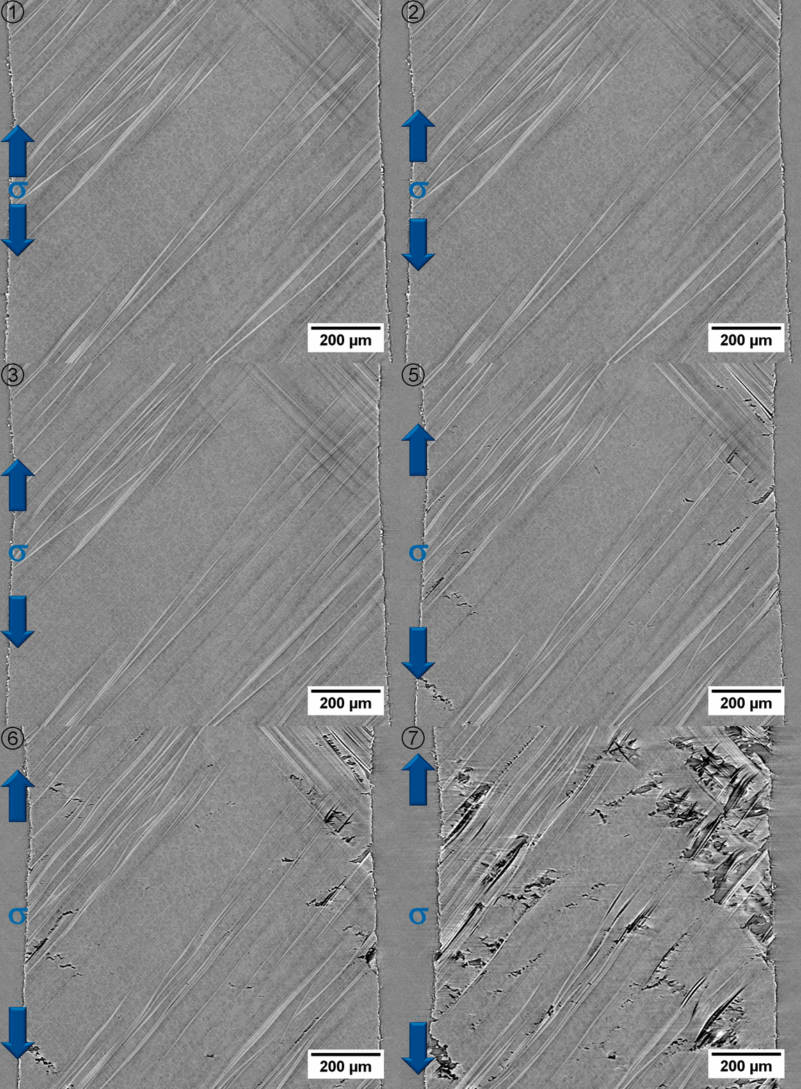
Fig. 1 shows the inhomogeneous damage distribution in a [±45]2s CFRP laminate tested under simple tension. Short cracks generate at the laminate edges and propagates towards the interior of the laminate generating a large crack density concentration at the borders. Through the laminate thickness the matrix cracking distribution is also heterogeneous and depends of other interacting damage mechanisms [1].

Fig. 1. 3D reconstruction of the tomographic volumes of a sample after deformation. Damage by matrix cracking is shown in red and the composite material in semitransparent.
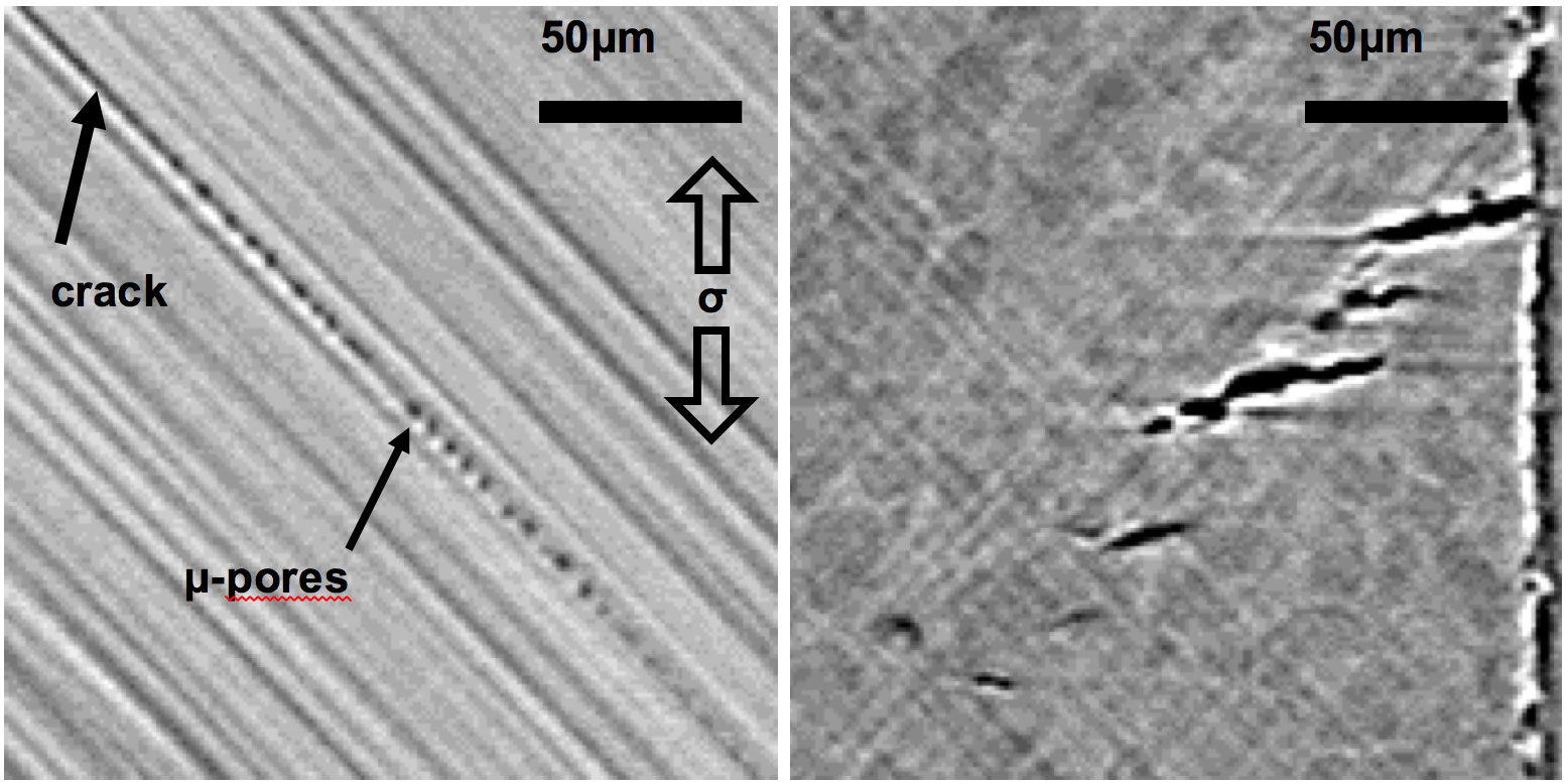
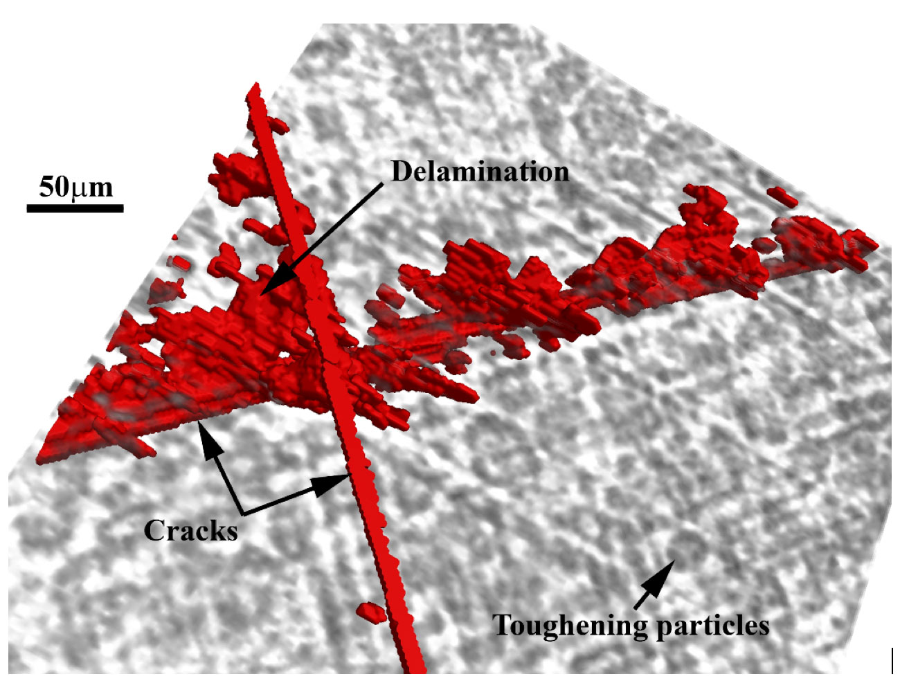
A closer look at one of the crack tips from in-situ synchrotron tomography data (Fig. 2), revealed that the crack propagates within the ply by the formation of micro-porosity which will eventually lead to cusps formation and finally to further crack propagation. The interface of this particular material was reinforced with toughening particles and the damage is in the form of decohesion between particles and matrix. These particles have an important role in delaying the crack propagation and delamination at the interface. The resin pockets in between these particles actually determine the way that damage is generated at the interface. The type of damage resembles the cusps formation but they rotate within the interface when they are observed through the interface from a +45º ply to a -45º ply. This is made visible in the 3D representation of the damage at the interface (Fig. 3), together with cracks at +45º and -45º at both sides of the interface and the toughening particles.

Fig. 2. (a) Detail of damage propagation mechanism ahead of a crack. (b) Matrix cracking at a ±45 interface with toughening particles

Fig. 3. 3D reconstruction of a sub-volume at a ±45º ply interface. Cracks at +45º and -45º from the interface are shown in red as well as the damage within the interface. The toughening particles at the interface are shown in semitransparent gray color.
[1] F. Sket, A. Enfedaque, C. Alton, C. González, J.M. Molina-Aldareguia, J. Llorca. Automatic quantification of matrix cracking and fiber rotation by X-ray computed tomography in shear-deformed fiber reinforced laminates. Compos. Sci. and Tech. 90 (2014) 129-138.
DOI: http://dx.doi.org/10.1016/j.compscitech.2013.10.022
[2] F. Sket, M. Rodríguez Hortalá, J. Molina Aldareguía, J. Llorca, E. Maire, G. Requena. In-situ tomographic investigation of damage development in ±45° carbon fibre reinforced laminates. Materials Science and Technology, Special Issue ‘Cavitation studies in materials: new insights from modern techniques in 2D/3D/4D characterisation’. Mater. Sci. Tech. Ser. 31(5) (2015) 587-593.
DOI: http://dx.doi.org/10.1179/1743284714Y.0000000561
[3] R. Muñoz, V. Martínez, F. Sket, C. González, J. Llorca. Mechanical behavior and failure micromechanisms of hybrid 3D woven composites in tension. Compos. Part A, 59, 93-104, 2014. DOI: http://dx.doi.org/10.1016/j.compositesa.2014.01.003


